In this article, we are going to tell you about Power Factor
Meters. Also, the types, structure, principles, and working methods of the power
factor meters are explained in detail. Also, power factor meter diagrams are
included.
Power Factor Meter
The power factor is the cosine of the angle (phase angle) ɸ
between the current passing through an AC circuit and the voltage found
parallel to the load.
Power factor meters are meters that measure the power factor
of a circuit and display it directly on its scale. These are called power
factor meters. In industries, if a consumer's power factor is less than the
standard power factor, then that consumer has to pay a penalty. (WAPDA Standard
Power Factor is currently 0.9 leaking) Power Factor Meters are installed in
industries to check or monitor individual load, any group of loads, or the
total load power factor of the industry. To avoid the penalty that has to be
paid in case of a low power factor.
Or
The ratio between the actual power (KW) and the external
power (KVA) of the load obtained in an AC circuit is called the power factor.
It is denoted by cos ɸ.
Power Factor Formula
Power Factor = True Power (KW)/Apparent Power (KVA)
Power Factor Cos ɸ = W/VA
Circuit of Power Factor
Wattmeter shows real power. The product of the ampere meter and
voltmeter readings is called the apparent power. The power factor of a single
fair load can be determined by connecting these three meters to the circuit
according to the shape. In this case, dividing the wattmeter reading by the
voltmeter and ampere meter reading gives the power factor of the load. In
practice, this method of determining the power factor is not easy. Therefore,
meters have been developed which can directly measure the power factor of AC
load.
 |
| Power Factor Meter |
Types of Power Factor Meters
1. Types of power factor meters in terms of supply
- Single Phase Power Factor Meters
- Three-Phase Power Factor Meters
- Power factor meters for three-phase balanced load
- Power factor meters for three phases unbalance load
2. Types of power factor meters in terms of structure
- Moving Coil Power Factor Meters
- Moving Iron Power Factor Meters
Single Phase Dynamometer Type P.F Meters
A device that measures the power factor in a single-phase AC
circuit, under the influence of the mechanical force found between the two
current-carrying conductors. The single-phase dynamometer type is called a
power factor. This power factor meter is also called a coming power coil or
power factor meter. It is also called a quadrature coil power factor meter. It
is also called crossed coil power factor meter.
Working Principle
The working principle of dynamometer type moving coil power factor meter (and to a considerable extent also the same) is the same. Which is a
dynamometer-type moving coil wattmeter. The torque coming into the meter's
moving system depends on the interaction of the magnetic field of the current
coils and the pressure coils. The motion of the moving system (clockwise or
counter-clockwise) depends on the nature of the load current, whether the load
current is inductive or resistive.
 |
| Single Phase Meters |
Theory
Suppose the power factor of the load with which the power factor
meter is fitted, the moving system (i.e. both moving coils P1 and P2)
for this value of the power factor is balanced by rotating ɸ angle from its
first position.
TP1 = KViL Cos ɸ * Sin Ѳ
TP2 = KViL Cos(90 - ɸ) * Sin(90 + Ѳ)
TP1 = TP2
Or Cos ɸ*Sin Ѳ =
Cos(90 - ɸ)*Sin(90 – Ѳ)
Or Tan Ѳ = Tan ɸ
Or Ѳ = ɸ
Three Phase Dynamometer Type P.F meter (for Balance Load)
Three Phase Dynamometer Type Power Factor Meter is used to
determine the power factor of three-phase balanced load.
Construction
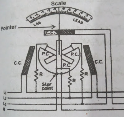
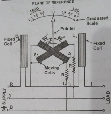
The figure shows the structure and connection of the three-phase
dynamometer type power factor for a balanced load. It has C1 and C2 double wire
loops of thick wire. These have been added to the series in a series of
three-round supply red phases.
The line current passes through both of them. Between these two
fixed coils, two pressure coils P1 and P2 are connected at 120° and fitted on a
pivoted spindle. Therefore, these two move together. In the P1 series, high
resistance R is added to connect between Y (i.e. Yellow) phase and R (i.e. Red)
phase.
 |
| Three Phase Meter |
Working Method
To generate torque in a single-phase supply, artificial
arrangements have to be made to obtain a phase shift.
But in this instrument, since the moving coils are connected to
two phases of the three-phase system (which differ from each other by 120°
electrical degrees depending on the difference), there is a need for artificial
phase shifting. Does not fall since both the coils are also mechanically
connected to 120. Therefore, in the case of balance load (depending on the value
of power factor of the load), rotating torque is generated in them. Which moves
the pointer from the unit position according to the phase angle of the circuit.
In the case of the capacitive load, this movement will be on the left. But in
practice, the leading power factor is very low. In the case of inductive load,
the pointer will move to the right.
Theory
T1 = KVRY iCos(30 + ɸ) Sin(60 + Ѳ)
T2 = KVRB iCos(30 - ɸ) Sin(120 + Ѳ)
Cos(30 - ɸ) Sin(60 + Ѳ) = Cos(30 - ɸ) Sin(120 + Ѳ)
Tree Phase Dynamometer Types P.F Meter (for Unbalance Load)
A three-wire three-phase system is usually balanced. Because this
supply is given to three-phase machines. The three-phase four-wire system, on
the other hand, is generally unbalanced. Because of this single-phase supply is
also obtained. Which is obtained from a single-phase and neutral. Thus the
system becomes unbalanced due to different loads on the three phases.
Working Principle
In the above sequence, two magnetic fields are formed, one due to
pressure coils and the other due to current coils. Both magnetic fields are
automatically rotating without any additional arrangement. Because the three
phases of three-phase supply are at 120 (electrical) degrees.
 |
| Three Phase Meter |
If the load is purely resistive (in this case the power factor is
unit), then the magnetic field of the coils and the magnetic field of the
current coils will be in phase with each other. And both will rotate at
synchronous speed. Therefore, no mechanical torque will be generated on the
moving system (pressure coils). That way she will stay still. And the measuring
needle unit will stand on the power factor. If there is some inductance or
capacitance in the load then both the magnetic fields are not in phase. Due to
this, the torque will act on the moving system and it will tell the
corresponding power factor by moving left or right depending on the power
factor of the load.
Thanks For Reading.
www.factsaboutworlda2z.website