In this article, we will tell you about Rectifier instruments and their types. Also, all the information on the Half or Full Wave rectifier is available here.
Rectifier Instruments
Rectifier instruments are no new type. Rather, they are
permanent magnet moving coil instruments. The only difference between these
instruments is that they have a rectifier unit attached to them. Which converts
AC to DC. This way the instrument can also measure such value with DC.
Rectifier instruments are commonly used in communication
circuits. They are especially suitable for measuring very low AC voltages and currents.
With the help of shunts, multipliers, and instrument transformers it can
increase the range of instruments.
Rectifier
A rectifier is a device or component that converts an AC
supply into a pulsating DC. Rectifier allows current to flow in only one
direction. So when AC passes through a rectifier, the current passes through
one of its directions. While the rectifier in the opposite direction offers
much higher resistance. And the flow of current from it stops.
 |
| Rectifier |
Types of Rectifier
The following two types of rectifiers are commonly used in
electrical instruments.
1. Metal Rectifiers
Types of Metal Rectifiers
1.1 Coper Oxide Rectifiers
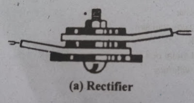
These rectifiers consist of copper discs with copper oxide
mounted on one side. In this way, current can pass from copper to copper oxide
but not in the opposite direction i.e. from copper oxide to copper. The
diameter of a disk is usually 1/2 inch. Multiple discs are joined together in
series and joined together by insulated bolts to form a larger unit. Brass
washers on both sides of the discs and metal fins for heat dissipation are also
installed. Copper oxide can pass a maximum of 0.1 amperes to 0.15 ampere
current at 8 volts per disc of a rectifier. The discs have to be enlarged for
more current or the rectifier is connected in parallel.
 |
| Copper Rectifiers |
1.2 Selenium Rectifiers
These rectifiers consist of iron discs. One side of them is
covered with selenium. In this way, the current flow from the iron to the
selenium but the current does not flow at all due to the high resistance of the
current in the opposite direction. The current and voltage rating of a disc of
the selenium rectifier is higher than that of the copper rectifier. One of its
discs can carry 0.2 to 0.3-ampere current at 16 to 18 volts.
 |
| Selenium Rectifiers |
2. Semiconductor Rectifiers
It is a circuit in which alternating current (AC) is converted to
pulsating DC using one or more diodes. The diode is made by combining a P-type
semiconductor and an N-type semiconductor. It is also called a PN junction.
 |
| Semiconductor Rectifiers |
Compared to other
rectifiers, they have the following features.
- They are small in size.
- The texture is simple, easy to prepare.
- Do not be disturbed by tremors and branches etc.
- Their current density is high.
- There is very little heat dissipation.
- Their age is double and their efficiency is high.
Types of Semiconductor Rectifiers
2.1 Half-Wave Rectifiers
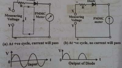
This instrument consists of a moving coil (PMMC) and a
diode. Diode converts AC supply to half-wave placing DC. When the measured
voltages are given between X and Y. When the positive half cycle of these voltages
reaches the diode, the resistance of the diode decreases to zero or very low
due to the forward bias. Therefore the current passes through it easily and
shows the PMMC instrument reading.
 |
| Half Wave Rectifiers |
When the diode gets a negative half cycle, the resistance of
the diode is very high due to the reverse bias. And no current passes through
it so the meter does not get current Meanwhile the meter control tries to bring
the spring pointer back to zero. But until the control torque returns to the
pointer, before the next positive off-cycle, the diode conducts and the meter
begins to receive current.
See Also: Click Here
In this way, the interval between the current received by
the meter is so short that the moving system of the meter is not affected by
it. Therefore this voltmeter deflates in terms of the average amount of supply
voltage. To calibrate the instrument key scale with the supply RMS quantity,
the average quantity displayed is multiplied by the form factor 1.11.
2.2 Full-Wave Rectifiers
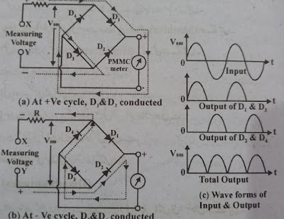
The full-wave rectifier consists of a PMMC and four diodes.
When the measured AC voltage is supplied to the X and Y terminals, the diodes D1
and D3 will be forward biased in case of a positive half cycle. And
the current will pass through them and get to the meter. And will embrace to
display meter readings. (Note that during this time diodes D2 and D4
become reverse bias. Therefore no current passes through them).
In the case of the negative half cycle, diodes D2
and D4 will be forward bisected and the current will pass through
them to the meter and the meter will start showing readings. (Note that during
this time diodes D1 and D3 are reverse biased. Therefore
no current will pass between them).
 |
| Full Wave Rectifiers |
In this way, both the half-cycle (positive and negative) conducts
from the bridge. Also, the direction of the current passing through the meter
during both half cycles is the same. However, the quantity does not remain the
same at different intervals. Therefore, its output is called Full-Wave
Pulsating DC. The PMMC meter provides straight and uniform deflection even on
this type of supply without swinging back and forth. This is because their
moving system does not follow the rapid changes in placement DC. Therefore this
voltmeter deflates in terms of the average amount of supply voltage. To
calibrate the scale of the instrument by the RMS quantity of the supply, the
average quantity shown is multiplied by the form factor 1.11.
Uses of Rectifiers
- Rectifier instruments can be used as ampere meters. But their current range is very small, from zero to 100 mille amperes. An instrument transformer is usually used to increase the range.
- These instruments can be used as voltmeters. It also has a low voltage range, from zero to 300 volts. But for low range, there is no scale linear so a step-up transformer is used.
Rectifier Advantages
- Can be used on both A and DC supplies.
- Used up to very low frequencies.
- It consumes very little power.
- Very suitable for measuring small amounts of current and voltage.
- Are more sensitive than ordinary AC instruments.
- Possess a high degree of accuracy.
- The textures are simple and reliable.
- They can also be used in high-power circuits.
- The magnetic field of the atmosphere does not affect them.
Rectifiers Disadvantages
- It can be used as an ampere meter directly in a very short range.
- They are used to measure low voltage. Also, enough voltage drops parallel to the diode.
- The scale of the rectifier is not linear for different values of resistance, voltage, and current. Therefore, their scale is narrower from the beginning.
- Give accurate readings only on a pure sine wave of supply.
- Temperature change has little effect on readings.
Disclaimer
All the information on the rectifier is given here
exactly. Types of Rectifier and Half / Full Wave Rectifier, Uses and Benefits
of Rectifier are explained.
If you have a suggestion or complaint, you can
contact us through the website.
www.factsaboutworlda2z.website
Thanks For Reading.